| Feature | Description |
|---|---|
| Blank Size | 10’ x 20’ (3.05 m x 6.10 m). We accommodate larger part volumes upon request. |
| Standard Lead Time | 3 business days |
| Sheet Thickness | 0.024” - 0.250” typical. We accommodate thicker or thinner gauges upon request. |
| General Tolerances | For single planes or flat parts, +/- 0.010” on edge to edge, edge to hole, and hole to hole features; +/- 0.010” on bend to edge/hole features. For multi-planed bent parts, +/- 0.030” for hole to hole/edge, edge to edge, and over-formed parts; +/- 1 degree for bend angles. |
| Braking (Hydraulic) | 10’ length, fingers from 3” - 6” |
| Braking (Magnetic) | 6 tons of magnetic pull across the entire beam, 5/8″ minimum reverse bend |
| Punching | 2″ diameter hole capacity, or larger upon request |
| Welding | Welded edges and seams, weldments, and assemblies |
Sheet Metal
CAPABILITIES
Sheet Metal Fabrication Services
Receive a fast quote for custom-formed sheet metal prototypes and production parts by uploading your CAD files. LS’s sheet metal solutions ensure the consistency, reliability, durability, and quality you expect, with various material and finishing options to support your specific needs.
Our Sheet Metal Process
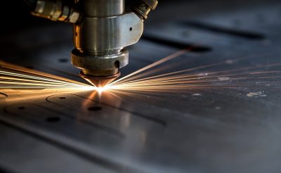
Blanking
Laser cutting, plasma cutting, CNC turret

Bending
Press brake, custom dies, stamping tools

Insert Installation
Full catalog of metric & standard PEM inserts and fasteners
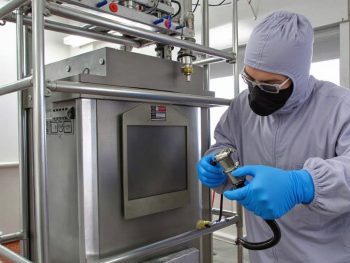
Secondary Finishing
Powder coating, anodizing, plating, painting
Fabrication Capabilities
Sheet Metal Materials Available
Aluminum 1100-H14,
Aluminum 5052-H32,
Aluminum 6061
Copper 101,
Copper C110,
Copper C110, H02,
Copper 260 (Brass)
Bronze 220,
Bronze 510
Stainless steel 301,
Stainless steel 304,
Stainless Steel 304 #4 brushed,
Stainless Steel 304, #8 mirror polish,
Stainless steel 316/316L,
Stainless Steel 316, #4 brushed
Steel 1018 (Low Carbon),
Steel 1045 (Hot Rolled),
Steel A569/ASTM A1011 (Hot Rolled),
AZ55 Galvalume,
A653 Galvanized,
1095 Spring Steel,
Steel A36,
Steel A36, pickled and oiled,
Steel A366/1008
Inconel 625,
Nickel Alloy 200,
Nickel Alloy 400
Titanium (Grade 2),
Titanium 6AI-4V (Grade 5)
Post Processing
Finishing Options for Sheet Metal

Minimal post-processing or treatment on parts is done.
The part surface is left with a smooth, matte appearance.
Type II (MIL-A-8625, Type II) creates a corrosion-resistant finish. Sheet metal parts can be anodized in different colors—clear, black, red, and gold are most common—and are usually associated with aluminum. Type III (MIL-A-8625, Type III, Class 1/2 "hardcoat") is thicker and creates a wear-resistant layer in addition to the corrosion resistance seen with Type II.
This sheet metal finish provides corrosion resistance and good conductivity properties. Chem film can be used as a base for paint and can leave surfaces yellow or gold. Adds very little thickness, about 0.00001”-0.00004.” Chem film will conform to MIL-DTL-5541, TYPE I/II.
This is a sheet metal fabrication process where powdered paint is sprayed onto a part that is then baked in an oven. This creates a strong, wear- and corrosion-resistant layer that is more durable than standard painting methods. A wide variety of colors are available to create the desired aesthetic. See examples of our options in our powder coating finishes gallery.
A sheet metal fabrication process that provides uniform nickel coating which offers protection from corrosion, oxidation, and wear on irregular surfaces. The finished part will be brighter. Thickness starts at .0001” and this finish conforms to MIL-C-26074.
Gold Plating provides good corrosion and tarnish resistance with excellent solderability. Default application specification is MIL-G-45204 & ASTM B488, CLASS 00, 0, OR 1 (Thickness 0.00002" - 0.00005").
Silver offers high solderability and electrical conductivity but is susceptible to tarnish on sheet metal parts. Conforms to AMS QQ-S-365D. Thickness is about 0.00002”- 0.0003.”
Design Guidelines
| Feature | Thickness Description |
|---|---|
| Minimum Bend | 1X MT |
| Minimum Hole to Edge Distance | 2X MT |
| Minimum Hole to Hole Distance | 6X MT |
| Minimum Bend Edge to Hole Distance | 6X MT |
| Minimum Feature to Countersink Distance | 8X MT |
| Minimum Countersink Depth | 0.6X MT |
| Relief Cuts | 1X MT |
| Corner Fillets | 0.5X MT |
